G3VM-41DR

Omron
Реле твердотельное - [SMT-4]; Конфиг: 1A; Вход: DC; Выход: AC, DC; Uкомм(DC): 40 В; Rоткр: 50 мОм; IDC: 2.5 А
развернуть ▼ свернуть ▲
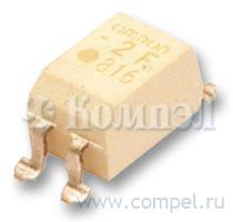
Технические характеристики

показать свернуть
Корпус SMT-4
Схема коммутации
Тип входа
Тип выхода
Напряжение коммутации DC
Сопротивление открытого канала
Ток коммутации
Напряжение изоляции
Нашли ошибку? Выделите её курсором и нажмите CTRL + ENTER

Файлы 2

показать свернуть
G3VM-41AR/DR MOS FET Relays DIP Higher power, 2.5-A switching with a 40-V load voltage, DIP package. Low 50 mΩ ON Resistance. • Continuous load current of 2.5 A. • Switches minute analog signals. G3VM-41AR/DR • Dielectric strength of 2,500 Vrms between I/O. RoHS compliant Note: The actual product is marked differently from the image shown here. ■ Application Examples ■ Terminal Arrangement/Internal Connections 4 • Communication equipment 3 Mold pin mark ∗ OMRON logo • Test & Measurement equipment Model name • Security equipment Pin 1 mark 932 LOT No. • Factory Automation equipment 1 • Power circuit 2 Note: The actual product is marked differently from the image shown here. ∗ The indentation in the corner diagonally opposite from the pin 1 mark is from a pin on the mold. ■ List of Models Package type Contact form DIP4 1a (SPST-NO) Load voltage (peak value) * Terminals PCB terminals Minimum package quantity Model Number per stick Number per tape and reel G3VM-41AR 40 V Surface-mounting terminals G3VM-41DR G3VM-41DR (TR) 100 --- --- 1,500 * The AC peak and DC value are given for the load voltage. ■ Absolute Maximum Ratings (Ta = 25°C) Input Item LED forward current Repetitive peak LED forward current LED forward current reduction rate LED reverse voltage Connection temperature Load voltage (AC peak/DC) Continuous load current (AC peak/DC) ON current reduction rate Pulse ON current Connection temperature Dielectric strength between I/O (See note 1.) Operating temperature Storage temperature Soldering temperature Output Symbol IF IFP ∆IF/°C VR TJ VOFF IO ∆IO/°C Iop TJ VI-O Ta Tstg --- Rating 30 1 −0.3 5 125 40 2.5 −25 7.5 125 2500 −40 to +85 −55 to +125 260 Unit mA A mA/°C V °C V A mA/°C A °C Vrms °C °C °C Measurement conditions 100 µs pulses, 100 pps Ta ≥ 25°C Ta ≥ 25°C t = 100 ms, Duty = 1/10 AC for 1 min With no icing or condensation With no icing or condensation 10 s Note: 1. The dielectric strength between the input and output was checked by applying voltage between all pins as a group on the LED side and all pins as a group on the light-receiving side. ■ Electrical Characteristics (Ta = 25°C) Input Item Symbol Minimum Typical Maximum LED forward voltage VF 1.18 1.33 1.48 Reverse current IR ----10 Capacity between terminals CT --70 --Trigger LED forward current IFT --0.5 3 Maximum resistance with output ON RON --50 150 Current leakage when the relay is open ILEAK ----1.0 Capacity between terminals COFF --300 --Capacity between I/O terminals CI-O --0.8 --Insulation resistance between I/O terminals RI-O 1000 ----Turn-ON time tON --0.8 5 Turn-OFF time tOFF --0.3 1 Output 1 Unit V µA pF mA mΩ µA pF pF MΩ ms ms Measurement conditions IF = 10 mA Note: VR = 5 V V = 0, f = 1 MHz IO = 1 A IF = 5 mA, IO = 2 A, t < 1s VOFF = 40 V V = 0, f = 1 MHz f = 1 MHz, VS = 0 V VI-O = 500 VDC, ROH ≤ 60% IF = 5 mA, RL = 200 Ω, VDD = 20 V (See note 2.) 2. Turn-ON and Turn-OFF Times IF 1 4 2 3 RL VDD VOUT IF VOUT 10% t ON 90% t OFF PDF
Документация на G3VM-41DR 

CSM_K137-E1-02

Дата модификации: 01.06.2012

Размер: 423.2 Кб

3 стр.

    Внимание! Точность указанного на сайте описания товара не может быть гарантирована. Для получения более полной и точной информации о товаре смотрите техническое описание (Datasheet) на сайте производителя.