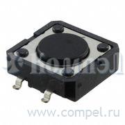
Серия кнопок без фиксации B3FS-4
Omron Co. - Electronic Components
Общие характеристики
| Раздел | Кнопки без фиксации |
| Электрическая цепь контактной группы |  |
| Максимальный рабочий ток |  |
| Максимальное рабочее напряжение |  |
| Тип актуатора |  |
| Относительная ориентация на плате |  |
| Особенности |  |
Документация на серию B3FS-4
New Product News
SMD Tactile Switch
B3FS-4
Surface-mounting Switches
with 12 x 12 mm size
• Surface-mounting device of B3F-4 series.
• Distinctive snapping action and extended mechanical/electrical
durability.
• Available in embossed taping packages for automatic mounting.
RoHS Compliant
■ Ordering Information
● List of Models
Type
Plunger type
12 x 12 mm
B3FS-4002P
Height
Operating force (OF)
Plunger color
4.3 mm
1.47 N
Black
Embossed taping
Model
Quantity per package
B3FS-4002P
1,000
Note: Order in multiples of the minimum order unit. Switches are not sold individually.
■ Specifications
● Ratings/Characteristics
Switching capacity
● Operating Characteristics
1 to 50 mA, 5 to 24 VDC (resistive load)
-25 to +70 degC at 60%RH max.
Ambient operating temperature
(with no icing or condensation)
Ambient operating humidity
35 to 85%RH (at +5 to +35 degC)
Contact configuration
SPST-NO
Contact resistance
100 m max. (initial value)
(rated: 1 mA, 5 VDC)
Insulation resistance
100 M (at 250 VDC)
Dielectric strength
500 VAC 50/60Hz for 1min
Vibration resistance
Malfunction: 10 to 55 Hz, 1.5-mm double
amplitude
Shock resistance
Destruction: 1,000 m/s2 {approx. 100 G} max.
Malfunction: 100 m/s2 {approx. 10 G} max.
Durability
3,000,000 operations min.
Weight
Approx. 1 g
Item
Model
Operating force (OF)
B3FS-4002P
1.470.49N {15050 gf}
Releasing force (RF)
0.15 N {15 gf} min.
Pretravel (PT)
0.250.15 mm
■ Dimensions
Note: 1. All units are in millimeters unless otherwise indicated. Unless otherwise specified, a tolerance of 0.4 mm applies to all dimensions.
Note: 2. The numbers used for terminals in the following graphics are indicated in the “Bottom View” diagram in the right. In this diagram, the Switch is
rotated so that the terminals are on the right and left-hand sides, and the OMRON logo appears the right way up.
2
1
4
3
(BOTTOM VIEW)
B3FS-4002P
ø7.1
PCB Pad (Example)
(TOP VIEW)
12±0.2
Terminal Arrangement/
Internal Connection
(Top View)
1
12±0.2 5±0.2
1
4
3
2
1
2.6±0.1 7.4±0.1
12±0.1
16.6±0.1
MAX0.4
4.3±0.2
0.1
15
1
�
 PDF
PDF
Товары серии B3FS-4