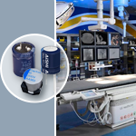
EECRG0V224H

SMDNot SMD Body shapeCoin type(multi-layer structure) Maximum operating voltage (V)3.6 Capacitance (F)0.22 Tolerance on capacitance (%)-20 to 80 Internal resistance(max.) (Ohm)50 Category temperature range (Cel)-25 to 85 Body diameter (mm)10.5 Occupied-length (mm)11.5 Occupied-width (mm)10.5 Occupied-height (mm)6 Lead(terminal) pitch (mm)10 Endurance (h)2000 Forming & packaging featureBulk(no lead/terminal forming),bag packing Quantity(min. packaging unit) (PCS.)200 Weight(Typ.) (g)1
развернуть ▼ свернуть ▲
  • Группа: Ионисторы  
  • Серия: RG  
  • Корпус:
  • Норма упаковки: 1  шт.
  • снято с производства

Технические характеристики

показать свернуть
Рабочее напряжение
Номинальная ёмкость
Рабочая температура
  Примечания: Electric Double Layer Capacitor, 3.6V, 80% +Tol, 20% -Tol, 220000uF, Through Hole Mount, 4541
Нашли ошибку? Выделите её курсором и нажмите CTRL + ENTER

Аналоги 1

показать свернуть
Тип Наименование Корпус Упаковка i Напряжение Ёмкость ESR Монтаж Шаг Траб Примечания Карточка
товара
P= JGAH5R5D224Z105B (JB)
 
на поддоне 1000 шт
 

Файлы 1

показать свернуть
Electric Double Layer Capacitors (Gold Capacitor) Stacked Coin Type Series : RG Low temperature assured product Features ● Endurance : +85 °C 2000 h temperature range : –40 °C to +85 °C ● RoHS compliant ● Category Recommended applications ● Backup of data/RTC of base station, electronic meter, and industrial equipment Specifications Category temp. range Maximum operating voltage Nominal capacitance Characteristics at low temperature Endurance Shelf life –40 °C to +85 °C 3.6 V.DC 0.22 F 1.0 F, 1.5 F Capacitance change ±30 % of initial measured value at +20 °C (at –40 °C) Internal resistance < 7 times of initial measured value at +20 °C (at –40 °C) After 2000 hours application of maximum operating voltage at +85 °C Capacitance change ±30 % of initial measured value at 20 °C 100 Ω or less (0.22 F) Internal resistance 40 Ω or less (1.0 F, 1.5 F) After 2000 hours storage at +85 °C without load (voltage) Capacitance change Capacitance change shall meet the specified limits for Endurance Internal resistance Internal resistance shall meet the specified limits for Endurance Dimensions in mm(not to scale) RG series (0.22 F) Terminal : V 3.0±0.5 11.5 max. 5.0±0.8 1.0±0.1 – 5.0±0.5 0.2±0.05 20.5 Max. 20.0±0.5 0.8±0.05 (1.7) f19.0±0.3 + 0.20±0.05 0.2±0.05 3.0±0.5 10.0±0.5 Sleeve 5.5±0.5 21.0 max. 4.0±0.3 0.2±0.05 6.0 max. 11.5 max. 010.5 max. f19.0±0.3 Terminal : H 3.5±0.3 6.5 max. Sleeve 5.0 max. 10.5 max. 0.8±0.05 (1.7) Terminal : H 5.0±0.3 Terminal : V RG series (1.0 F, 1.5 F) 1.0±0.1 (Unit : mm) Characteristics list Min. Category Maximum Internal Mass Capacitance operating Capacitance packaging temp. resistance Recommended ✽1 Parts number (Reference value) tolerance voltage q'ty range (F) (Initial specified value) discharge current (F) (g) (V.DC) (pcs) (°C) (Ω) at 1 kHz 0.22 0.176 to 0.396 300 µA or less EECRG0V224( )N 1.0 200 < 50 –40 to +85 3.6 1.0 0.8 to 1.8 < 20 1 mA or less EECRG0V105( )N 4.1 100 1.5 1.2 to 2.7 < 20 1 mA or less EECRG0V155( )N 4.2 100 ( ) : Please use V or H to indicate terminal type. ✽1 The recommended discharge current is a reference value. Please design your equipment(circuit) in consideration of IR drop. Do not use reflow soldering. Please refer to the page of “Application guidelines”. Design and specifications are each subject to change without notice. Ask factory for the current technical specifications before purchase and/or use. Should a safety concern arise regarding this product, please be sure to contact us immediately. 02 Aug. 2016 PDF
Документация на EECRG0V105H 

N_GC_RG_N_E.indd

Дата модификации: 25.08.2016

Размер: 45.6 Кб

1 стр.

    Внимание! Точность указанного на сайте описания товара не может быть гарантирована. Для получения более полной и точной информации о товаре смотрите техническое описание (Datasheet) на сайте производителя.