EEEFK0J133SM

Конденсатор алюминиевый 6.3 В x 13000 мкФ ±20%, SMD, -55...105 °C, 5000 ч
развернуть ▼ свернуть ▲

Технические характеристики

показать свернуть
Ёмкость номинальная
Допуск по ёмкости
Напряжение номинальное
Температура рабочая
Срок службы
Диаметр корпуса
Высота корпуса
Способ монтажа
Эквивалентное последовательное сопротивление
Ток пульсаций низких частот
Диаметр x Высота 18×18×19 мм
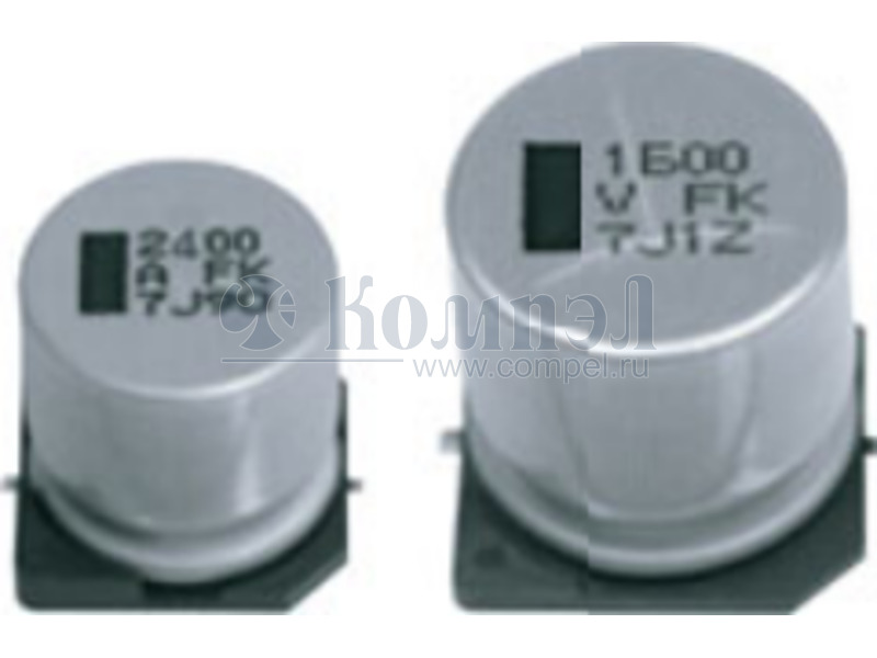
  Примечание: Aluminum Electrolytic Capacitor, Polarized, Aluminum (wet), 6.3V, 20% +Tol, 20% -Tol, 13000uF, Surface Mount, 7575
Нашли ошибку? Выделите её курсором и нажмите CTRL + ENTER

Аналоги 1

показать свернуть
Тип Наименование Корпус Упаковка i Ёмкость Допуск Напряжение Температура рабочая Срок службы Диаметр Высота Способ монтажа Шаг ESR Импеданс Ток пульсаций НЧ Ток пульсаций ВЧ Применение Примечание Карточка
товара
A+ EEEFK0J133SV (PAN)
 
75 шт Aluminum Electrolytic Capacitor, Polarized, Aluminum (wet), 6.3V, 20% +Tol, 20% -Tol, 13000uF, Surface Mount, 7575

Файлы 2

показать свернуть
Aluminum Electrolytic Capacitors Surface Mount Type FKS series (Medium-size) High temperature Lead-Free reflow Features ● ● ● ● ● Endurance:105 ℃ 5000 h High capacitance : 20 to 80 % higher than FK series, large capacitance up to 13000 μF Vibration-proof product (30G guaranteed) is available upon request AEC-Q200 compliant RoHS compliant Specifications Category temp. range Rated voltage range Capacitance range Capacitance tolerance Leakage current Dissipation factor (tan δ) Characteristics at low temperature Endurance Shelf life Resistance to soldering heat –55 ℃ to +105 ℃ 6.3 V to 35 V 750 μF to 13000 μF ±20 % (120 Hz / +20 ℃) I ≦ 0.01 CV(μA) After 2 minutes Please see the attached characteristics list Rated voltage (V) 6.3 10 16 25 35 Z (–25 ℃) / Z (+20 ℃) 2 2 2 2 2 (Impedance ratio at 120 Hz) Z (–40 ℃) / Z (+20 ℃) 3 3 3 3 3 Z (–55 ℃) / Z (+20 ℃) 4 4 4 3 3 After applying rated working voltage for 5000 hours at +105 ℃ ± 2 ℃ and then being stabilized at +20 ℃, capacitors shall meet the following limits. Capacitance change Within ±30 % of the initial value Dissipation factor(tan δ) ≦ 300 % of the initial limit Leakage current Within the initial limit After storage for 1000 hours at +105 °C ± 2 °C with no voltage applied and then being stabilized at +20 °C, capacitors shall meet the limits specified in endurance. (With voltage treatment) Capacitance change Within ±30 % of the initial value Dissipation factor(tan δ) ≦ 200 % of the initial limit Leakage current Within the initial limit After reflow soldering and then being stabilized at +20 ℃, capacitors shall meet the following limits. Capacitance change Within ±10 % of the initial value Dissipation factor(tan δ) Within the initial limit Leakage current Within the initial limit Frequency correction factor for ripple current Frequency (Hz) Correction factor 120 0.75 10 k 0.95 Dimensions Example : 6.3 V 3500 μF Marking color : BLACK K A±0.2 H Mark for Lead-Free (P) Series identification L products (Black dot) (I) Capacitance (μF) B±0.2 3500 j FK 0.3 max. øD±0.5 Negative polarity marking (–) 100 k to 1.00 W Pressure Relief ()Reference size Rated voltage code Lot number R.voltage code j A C 6.3 10 16 E V Unit:V 25 35 (I) Marking 1k 0.90 Unit:mm Size code øD L A, B H13 J16 K16 K21 12.5 16.0 18.0 18.0 13.5±0.5 16.5±0.5 16.5±0.5 21.5±0.5 13.5 17.0 19.0 19.0 H 15.0 19.0 21.0 21.0 max. max. max. max. I W P K 4.7 5.5 6.7 6.7 0.90±0.3 1.20±0.3 1.20±0.3 1.20±0.3 4.4 6.7 6.7 6.7 0.70±0.3 0.70±0.3 0.70±0.3 0.70±0.3 ・The dimensions of the vibration-proof products, please refer to the page of the mounting specification. Design and specifications are each subject to change without notice. Ask factory for the current technical specifications before purchase and/or use. Should a safety concern arise regarding this product, please be sure to contact us immediately. 06-Dec-19 PDF
Документация на EEEFK1V302SV 

Series catalog

Дата модификации: 19.08.2021

Размер: 604.1 Кб

10 стр.

Aluminum Electrolytic Capacitors (SMD Type) Surface Mount Type Series : Medium-size FKS Type : V High temperature Lead-Free reflow Features ● Endurance : 105 °C 5000 h ● High capacitance : 20 to 80 % higher than FK series, ● Vibration-proof product is available upon request. ● RoHS compliant large capacitance up to 13000 μF Specifications Category temperature range Rated voltage range Capacitance range Capacitance tolerance Leakage current Dissipation factor (tan d) Characteristics at low temperature Endurance Shelf life Resistance to soldering heat AEC-Q200 –55 °C to +105 °C 6.3 V.DC to 35 V.DC 750 μF to 13000 μF ±20 % (120 Hz/+20 °C) I < 0.01 CV (μA) After 2 minutes Please see the attached characteristics list V.DC 6.3 10 16 25 35 Z(–25 °C)/Z(+20 °C) 2 2 2 2 2 (Impedance ratio at 120 Hz) Z(–40 °C)/Z(+20 °C) 3 3 3 3 3 Z(–55 °C)/Z(+20 °C) 4 4 4 3 3 After applying rated working voltage for 5000 hours at +105 °C±2 °C and then being stabilized at +20 °C, Capacitors shall meet the following limits. Capacitance change Within ±30 % of the initial value < 300 % of the initial limit tan d DC leakage current Within the initial limit After storage for 1000 hours at +105 °C±2 °C with no voltage applied and then being stabilized at +20 °C, capacitors shall meet the limits specified in Endurance (With voltage treatment) Capacitance change Within ±30 % of the initial value < 200 % of the initial limit tan d DC leakage current Within the initial limit After reflow soldering and then being stabilized at +20 °C, capacitors shall meet the following limits. Capacitance change Within ±10 % of the initial value tan d Within the initial limit DC leakage current Within the initial limit AEC-Q200 compliant Frequency correction factor for ripple current Frequency (Hz) Correction factor 120 0.75 10 k 0.95 Capacitance (μF) 3500 j FK Series identification Mark for Lead-Free products (Black dot) K (P) + L Pressure Relief (I) Negative polarity marking (–) A±0.2 – H 0D±0.5 0.3 max. (I) Dimensions Example : 6.3 V.DC 3500 μF Marking color : BLACK W ( ) Reference (Unit : mm) Rated voltage code Size 0D code Lot number R. Voltage (V.DC) Code 100 k to 1.00 B±0.2 Marking 1k 0.90 6.3 10 16 25 35 j A C E V H13 J16 K16 K21 12.5 16.0 18.0 18.0 L A, B H I W P K 13.5±0.5 16.5±0.5 16.5±0.5 21.5±0.5 13.5 17.0 19.0 19.0 15.0 max. 19.0 max. 21.0 max. 21.0 max. 4.7 5.5 6.7 6.7 0.90±0.3 1.20±0.3 1.20±0.3 1.20±0.3 4.4 6.7 6.7 6.7 0.70±0.30 0.70±0.30 0.70±0.30 0.70±0.30 Design and specifications are each subject to change without notice. Ask factory for the current technical specifications before purchase and/or use. Should a safety concern arise regarding this product, please be sure to contact us immediately. 00 May. 2017 PDF
Документация на серию FKS_SMD 

N_AEC_V-FKS中形_E.indd

Дата модификации: 27.03.2019

Размер: 79.8 Кб

3 стр.

    Внимание! Точность указанного на сайте описания товара не может быть гарантирована. Для получения более полной и точной информации о товаре смотрите техническое описание (Datasheet) на сайте производителя.