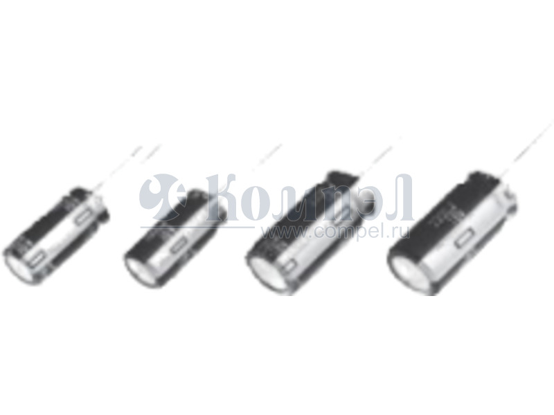
EEUFC1H102C

Конденсатор алюминиевый 50 В x 1000 мкФ ±20%, -55...105 °C
развернуть ▼ свернуть ▲
 

Технические характеристики

показать свернуть
Ёмкость номинальная
Допуск по ёмкости
Напряжение номинальное
Температура рабочая
Ток пульсаций низких частот
  Примечание: Aluminum Electrolytic Capacitor, Polarized, Aluminum (wet), 50V, 20% +Tol, 20% -Tol, 1000uF, Through Hole Mount
Нашли ошибку? Выделите её курсором и нажмите CTRL + ENTER

Файлы 1

показать свернуть
Aluminum Electrolytic Capacitors/ FC Country of Origin Radial Lead Type Series: FC Type: Japan Malaysia China A ■ Features ● Endurance : 105 °C 1000 h to 5000 h ● Low impedance ● RoHS directive compliant ■ Specifications –55 to +105 °C Category Temp. Range 6.3 to 100 V.DC Rated W.V. Range 1.0 to 15000 µF Nominal Cap. Range ±20 % (120 Hz/+20 °C) Capacitance Tolerance I < 0.06 CV or 3 (µA) after 2 minutes application of rated working voltage at +20 °C (Whichever is greater) DC Leakage Current W.V. (V) 6.3 10 16 25 35 50 63 100 tan d 0.22 0.19 0.16 0.14 0.12 0.10 0.08 0.07 tan d For capacitance value > 1000 µF, add 0.02 per every 1000 µF. After following life test with DC voltage and +105±2°C ripple current value applied (The sum of DC and ripple peak voltage shall not exceed the rated working voltage), the capacitors shall meet the limits specified bellow. Duration : 1000 hours (f4 to 6.3), 2000 hours (f8), 3000 hours (f10), 5000 hours (f12.5 to 18) Post test requirement at +20 °C Endurance Capacitance change ±20 % of initial measured value tan d <200 % of initial specified value DC leakage current < initial specified value After storage for 1000 hours at +105±2 °C with no voltage applied and then being stabilized at +20 °C, capacitor shall meet the limits specified in Endurance. (With voltage treatment) Shelf Life ■ Frequency correction factor for ripple current W.V.(V.DC) Frequency (Hz) Capacitance (µF) 1.0 to 6.3 to 100 60 120 1k 10 k 100 k 330 0.55 0.65 0.85 0.90 1.0 390 to 1000 0.70 0.75 0.90 0.95 1.0 1200 to 2200 0.75 0.80 0.90 0.95 1.0 2700 to 15000 0.80 0.85 0.95 1.00 1.0 ■ Dimensions in mm (not to scale) Sleeve f10< fd±0.05 f8> + (>6.3 mm dia) Vent fD+0.5 max. 3 min. fD+0.5 max. P±0.5 14 min. L✽ P±0.5 – But exclude 7 mm height product L<16 : L+1.0 max. L>20 : L+2.0 max. ✽ f8҂15, f16҂15, f18҂15 : L+1.5 max. (mm) L>11 Body Dia. fD 4 5 6.3 8 L=7 10 12.5 16 18 4 5 6.3 15 to 25 30 to 40 Body Length L Lead Dia. fd 0.45 0.5 0.5 0.6 0.6 0.6 0.8 0.8 0.8 0.45 0.45 0.45 Lead space P 1.5 2 2.5 3.5 5.0 5.0 5.0 7.5 7.5 1.5 2 2.5 Design and specifications are each subject to change without notice. Ask factory for the current technical specifications before purchase and/or use. Should a safety concern arise regarding this product, please be sure to contact us immediately. May. 2006 PDF
Документация на EEUFC1H102C 

Дата модификации: 09.11.2006

Размер: 722.1 Кб

10 стр.

    Внимание! Точность указанного на сайте описания товара не может быть гарантирована. Для получения более полной и точной информации о товаре смотрите техническое описание (Datasheet) на сайте производителя.