
08 сентября 2020
статья
| Ёмкость номинальная |  | |
|---|---|---|
| Допуск по ёмкости |  | |
| Напряжение номинальное |  | |
| Температура рабочая |  | |
| Диаметр корпуса |  | |
| Высота корпуса |  | |
| Способ монтажа |  | |
| Эквивалентное последовательное сопротивление |  | |
| Ток пульсаций низких частот |  | |
| Диаметр x Высота | 5×5×5.3 мм | |
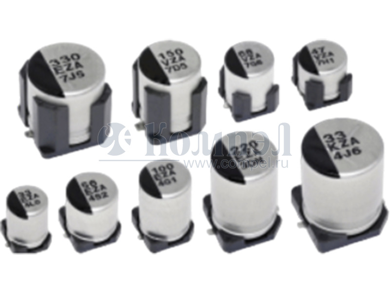
| Примечание: Aluminum Electrolytic Capacitor, Polarized, Aluminum (solid Polymer), 25V, 20% +Tol, 20% -Tol, 56uF, Surface Mount, 2121 | ||
| Тип | Наименование | Корпус | Упаковка | i | Ёмкость | Допуск | Напряжение | Температура рабочая | Срок службы | Диаметр | Высота | Способ монтажа | Шаг | ESR | Импеданс | Ток пульсаций НЧ | Ток пульсаций ВЧ | Применение | Примечание | Карточка товара |
|---|---|---|---|---|---|---|---|---|---|---|---|---|---|---|---|---|---|---|---|---|
| A+ | EEEFN1E560UR (PAN) | — | в ленте 1000 шт |
|  |  |  |  |  |  |  |  | — |  | — |  | — | — | V-FN, 25V, 56uF, 105°C, 2000h, 5x5.8mm, ripple 160mArms, 0.7Ohm | |
| A+ | EEHZC1E560P (PAN) | — | в ленте 1000 шт |
|  |  |  |  |  |  |  |  | — |  | — |  | — | — |  | |
| A+ | EEHZF1H560P (PAN) | — |  |  |  |  | — |  |  |  | — |  | — |  | — | — | Aluminum Electrolytic Capacitor, Polarized, Aluminum (solid Polymer), 50V, 20% +Tol, 20% -Tol, 56uF, Surface Mount, 3333 | |||
| A+ | EEHZF1H560V (PAN) | — |  |  |  |  | — |  |  |  | — |  | — |  | — | — | Aluminum Electrolytic Capacitor, Polarized, Aluminum (solid Polymer), 50V, 20% +Tol, 20% -Tol, 56uF, Surface Mount, 3333 | |||
| A+ | 25SVF56M (PAN) | — | 1000 шт |
|  |  |  |  |  |  |  |  | — |  | — |  | — | — | High Voltage, Temp and Capacitance | |
| A+ | 25SVP56M (PAN) | — | 1 шт |
|  |  |  |  |  |  |  |  | — |  | — |  | — | — |  | |
| A+ | 25SVPF56M (PAN) | — | в ленте 1000 шт |
|  |  |  |  |  |  |  |  | — |  | — |  | — | — | High Voltage / Large capacitance | |
| A+ | EEHZK1V560P (PAN) | — | в ленте 1000 шт |
|  |  |  |  |  |  |  |  | — |  | — |  | — | — |  | |
| A+ | EEH-ZA1E560P (PAN) | — |  |  |  |  |  |  |  |  | — |  | — |  | — | — |  | |||
| A+ | EEHAZF1H560 (PAN) | — | 200 шт |
|  |  |  |  |  |  |  |  |  |  | — |  | — | — | High temprature than ZC series, Radial type | |
| A+ | EEH-ZC1E560P (PAN) | — |  |  |  |  |  |  |  |  | — |  | — |  | — | — |  | |||
| A+ | EEHZA1E560P (PAN) | — | в ленте 1000 шт |
|  |  |  |  |  |  |  |  | — |  | — |  | — | — |  | |
| A+ | EEH-ZF1H560V (PAN) | — |  |  |  |  |  |  |  |  | — |  | — |  | — | — |  | |||
| A+ | EEH-ZK1E560UR (PAN) | — |  |  |  |  |  |  |  |  | — |  | — |  | — | — |  | |||
| A+ | EEH-ZK1V560P (PAN) | — |  |  |  |  |  |  |  |  | — |  | — |  | — | — |  | |||
| A+ | EEEFK1E270SR (PAN) | — | 1000 шт |
|  |  |  |  |  |  |  |  | — |  | — |  | — | — | Aluminum Electrolytic Capacitor, Polarized, Aluminum (wet), 25V, 20% +Tol, 20% -Tol, 27uF, Surface Mount, 1616 |
Внимание! Точность указанного на сайте описания товара не может быть гарантирована. Для получения более полной и точной информации о товаре смотрите техническое описание (Datasheet) на сайте производителя.