LP-NSML175

DOCUMENT: M20540 REV LETTER: D PAGE NO: 1 OF 2 DATE: 2019-09-10 PART NUMBER: Polymer PTC Devices Wayon Electronics Co., Ltd. No.1001,Shiwan 7th Road,Pudong,Shanghai 201202,P.R.China Tel: 86-21-50968308 Fax: 86-21-50968310 Surface mount fuses E-mail: market@way-on.com LP-NSML175 Http://www.way-on.com Features Small size of 1206 Low risistance Lead-free and compliant with the European Unio...
развернуть ▼ свернуть ▲

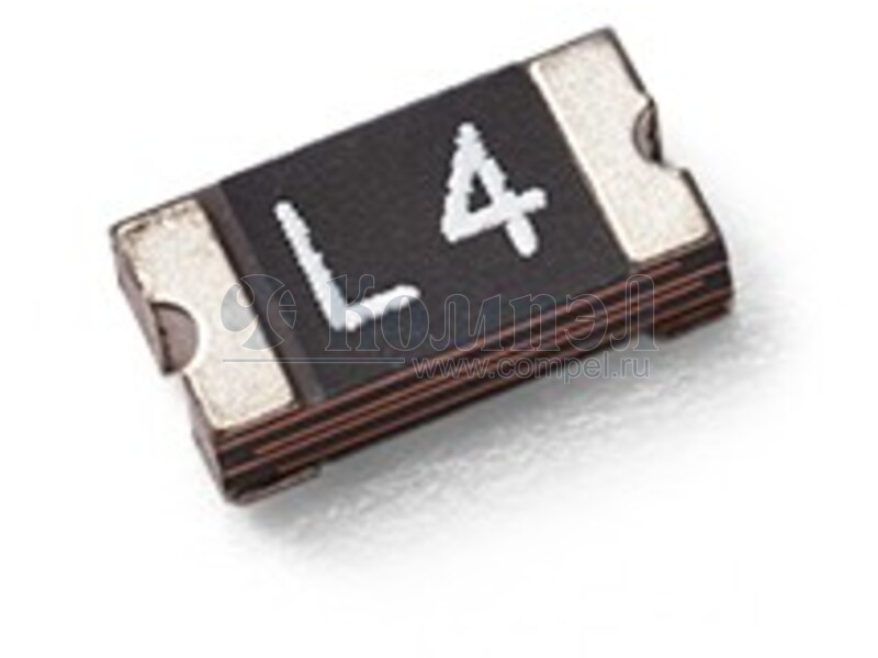
Технические характеристики

показать свернуть
Ток удержания
Ток срабатывания
Рабочий ток (max)
Рабочее напряжение (max)
Рабочее сопротивление
Время срабатывания
Корпус
Нашли ошибку? Выделите её курсором и нажмите CTRL + ENTER

Файлы 1

показать свернуть
DOCUMENT: M20540 REV LETTER: D PAGE NO: 1 OF 2 DATE: 2019-09-10 PART NUMBER: Polymer PTC Devices Wayon Electronics Co., Ltd. No.1001,Shiwan 7th Road,Pudong,Shanghai 201202,P.R.China Tel: 86-21-50968308 Fax: 86-21-50968310 Surface mount fuses E-mail: market@way-on.com LP-NSML175 Http://www.way-on.com Features Small size of 1206 Low risistance Lead-free and compliant with the European Union RoHS Directive 2011/65/EU Fast time-to-trip Agency Recognition: UL、CSA 、TUV Product Dimensions (mm) Part number A B C D E Max. Max. Max. Min. Min. Part Marking 3.50 1.80 0.70 0.25 0.10 J LP-NSML175 Electrical Characteristics IH Part number LP-NSML175 IT Vmax Imax Ttrip Pd typ Rmin R1max (A) (A) (V) (A) Current(A) Time(S) (W) (Ω) (Ω) 1.75 5.50 6 50 8.00 60 1.2 0.003 0.028 IH=Hold current: maximum current at which the device will not trip at 25℃ still air. IT=Trip current: minimum current at which the device will always trip at 25℃ still air. Vmax=Maximum voltage device can withstand without damage at rated current. Imax=Maximum fault current device can withstand without damage at rated voltage. Ttrip=Maximum time to trip(s) at assigned current. Pdtyp=Typical power dissipation: typical amount of power dissipated by the device when in state air environment. Rmin=Minimum device resistance at 25℃ prior to tripping. R1max=Maximum device resistance measured in the nontripped state 1 hour post reflow. Thermal Derating Maximum ambient operating temperature(℃) LP-NSML175 -40 -20 0 20 25 40 50 60 70 85 Hold Current (A) 2.34 2.05 1.89 1.80 1.75 1.44 1.31 1.20 1.00 0.72 Trip Current (A) 6.82 6.10 5.60 5.55 5.50 4.30 4.05 3.60 3.00 2.15 Solder Reflow Recommendations C Solder Pad Layouts Part number A B C (mm) (mm) (mm) 1.80 1.00 1.80 LP-NSML175 B A B * Recommended reflow methods: IR, Vapor phase, hot air oven. * Devices can be cleaned using standard industry methods and solvents. Notes:  If reflow temperatures exceed the recommended profile, devices may not meet the performance requirements.  Devices are not designed to be wave soldered to the bottom side of the board. Package Information Tape & Reel: 4000pcs per reel. Effectivity: Reference documents shall be the issue in effect on the date of invitation for bid. Caution: Operation beyond the rated voltage or current may result in rupture electrical arcing or flame. Specifications are subject to change without notice. Page 1 of 2 PDF
Документация на LP-NSML175 

Shanghai Changyuan Wayon Circuit protection Co., Ltd

Дата модификации: 13.12.2022

Размер: 259.3 Кб

2 стр.

    Внимание! Точность указанного на сайте описания товара не может быть гарантирована. Для получения более полной и точной информации о товаре смотрите техническое описание (Datasheet) на сайте производителя.