Серия алюминиевых конденсаторов FK

Общие характеристики

Раздел Алюминиевые конденсаторы
Допуск по ёмкости
Температура рабочая
Способ монтажа
Срок службы
Эквивалентное последовательное сопротивление

Документация на серию FK

Aluminum Electrolytic Capacitors Surface Mount Type Halogen-free FK series High temperature Lead-Free reflow (suffix : A✽) Features ● ● ● ● ● Country of origin Endurance:105 ℃ 2000 h Low impedance (40 % to 60 % less than FC series) Miniaturized (30 % to 50 % less than FC series) AEC-Q200 compliant RoHS compliant ● Malaysia Specifications Category temp. range Rated voltage range Capacitance range Capacitance tolerance Leakage current Dissipation factor (tan δ) Characteristics at low temperature Endurance Shelf life Resistance to soldering heat –55 ℃ to +105 ℃ 6.3 V to 35 V 33 μF to 1500 μF ±20 % (120 Hz / +20 ℃) I ≦ 0.01 CV or 3 (μA) After 2 minutes (Whichever is greater) Please see the attached characteristics list Rated voltage (V) 6.3 10 16 25 35 Z (–25 ℃) / Z (+20 ℃) 2 2 2 2 2 (Impedance ratio at 120 Hz) Z (–40 ℃) / Z (+20 ℃) 3 3 3 3 3 Z (–55 ℃) / Z (+20 ℃) 4 4 4 3 3 After applying rated working voltage for 2000 hours at +105 ℃ ± 2 ℃ and then being stabilized at +20 ℃, capacitors shall meet the following limits. Capacitance change Within ±30 % of the initial value Dissipation factor(tan δ) ≦ 200 % of the initial limit Leakage current Within the initial limit After storage for 1000 hours at +105 ℃ ± 2 ℃ with no voltage applied and then being stabilized at +20 ℃, capacitors shall meet the limits specified in endurance. (With voltage treatment) After reflow soldering and then being stabilized at +20 ℃, capacitors shall meet the following limits. Capacitance change Within ±10 % of the initial value Dissipation factor(tan δ) Within the initial limit Leakage current Within the initial limit Frequency correction factor for ripple current Freq.(Hz) 33 to 470 680 to 1500 120 1k 10 k 100 k to 0.65 0.70 0.85 0.90 0.95 0.95 1.00 1.00 Dimensions 0.3 max. L Mark for Lead-Free R. voltage code j A C 6.3 10 16 Rated voltage code E V Unit:V 25 35 (P) (I) Series identification W Pressure Relief (ø10 and larger) products (Black dot) Lot number H Capacitance (μF) H øD±0.5 Negative polarity marking (–) 100 j FK A±0.2 K Example : 6.3 V 100 μF Marking color : BLACK (I) Marking B±0.2 Cap.(μF) ()Reference size Unit:mm Size code øD L A, B H I W D 6.3 5.8±0.3 6.6 7.8 max. 2.6 0.65±0.1 1.8 0.35 D8 6.3 7.7±0.3 6.6 7.8 max. 2.6 0.65±0.1 1.8 0.35 8.3 9.5 max. 2.2 0.35 E 8.0 6.2±0.3 F 8.0 10.2±0.3 G P K +0.15 ー0.20 +0.15 ー0.20 +0.15 ー0.20 3.4 0.65±0.1 8.3 10.0 max. 3.4 0.90±0.2 3.1 0.70±0.2 10.0 10.2±0.3 10.3 12.0 max. 3.5 0.90±0.2 4.6 0.70±0.2 Design and specifications are each subject to change without notice. Ask factory for the current technical specifications before purchase and/or use. Should a safety concern arise regarding this product, please be sure to contact us immediately. 13-Mar-20 PDF
Документация на EEEFK0J102AL 

Series catalog

Дата модификации: 24.09.2021

Размер: 513.9 Кб

9 стр.

Aluminum Electrolytic Capacitors Surface Mount Type FK series V type Features ● ● ● ● ● ● Endurance:105 ℃ 2000 h to 5000 h Low impedance(40 % to 60 % less than FC series) Miniaturized (30 % to 50 % less than FC series) Vibration-proof product (30G guaranteed) is available upon request(φ6.3 ≦) AEC-Q200 compliant RoHS compliant Specifications Category temp. range Rated voltage range Capacitance range Capacitance tolerance Leakage current Dissipation factor (tan δ) Characteristics at low temperature Endurance Shelf life Resistance to soldering heat –55 ℃ to +105 ℃ 6.3 V to 100 V 3.3 μF to 6800 μF ±20 % (120 Hz / +20 ℃) I ≦ 0.01 CV or 3 (μA) After 2 minutes (Whichever is greater) Please see the attached characteristics list Rated voltage (V) 6.3 10 16 25 35 50 63 80 100 Z (–25 ℃) / Z (+20 ℃) 2 2 2 2 2 2 2 2 2 (Impedance ratio at 120 Hz) Z (–40 ℃) / Z (+20 ℃) 3 3 3 3 3 3 3 3 3 Z (–55 ℃) / Z (+20 ℃) 4 4 4 3 3 3 3 3 3 After applying rated working voltage for 2000 hours at +105 ℃ ± 2 ℃ and then being stabilized at +20 ℃, capacitors shall meet the following limits. (≧ φ12.5 and suffix “G” in φ8×10.2, φ10×10.2 are 5000 hours) Capacitance change Within ±30 % of the initial value (Suffix “G” is 35 %) Dissipation factor(tan δ) ≦ 200 % of the initial limit (Suffix “G” is 300 %) Leakage current Within the initial limit After storage for 1000 hours at +105 ℃ ± 2 ℃ with no voltage applied and then being stabilized at +20 ℃, capacitors shall meet the limits specified in endurance. (With voltage treatment) After reflow soldering and then being stabilized at +20 ℃, capacitors shall meet the following limits. Capacitance change Within ±10 % of the initial value Dissipation factor(tan δ) Within the initial limit Leakage current Within the initial limit Frequency correction factor for ripple current Frequency (Hz) Correction factor 50, 60 0.70 120 0.75 Mark for Lead-Free j FK Lot number R. voltage code j A C E V 6.3 10 16 25 35 Series identification Rated voltage code Unit:V 50 63 80 100 Size code B C D D8 E F G H13 J16 K16 φD 4.0 5.0 6.3 6.3 8.0 8.0 10.0 12.5 16.0 18.0 L 5.8±0.3 5.8±0.3 5.8±0.3 7.7±0.3 6.2±0.3 10.2±0.3 10.2±0.3 13.5±0.5 16.5±0.5 16.5±0.5 A, B 4.3 5.3 6.6 6.6 8.3 8.3 10.3 13.5 17.0 19.0 H 5.5 max. 6.5 max. 7.8 max. 7.8 max. 9.5 max. 10.0 max. 12.0 max. 15.0 max. 19.0 max. 21.0 max. (I) K W Pressure Relief (φ10 and larger) Capacitance (μF) H J K 2A (P) L Negative polarity marking (–) 3300 H Rated voltage code (I) ≧ φ12.5 Lot number Series identification A±0.2 0.3 max. φD±0.5 Negative polarity marking (–) Capacitance (μF) 22 j FK 100 k to 1.00 Dimensions Example : 6.3 V 22 μF, 6.3 V 3300 μF Marking color : BLACK ≦ φ10 10 k 0.95 B±0.2 Marking 1k 0.90 ()Reference size I 1.8 2.2 2.6 2.6 3.4 3.4 3.5 4.7 5.5 6.7 W 0.65±0.1 0.65±0.1 0.65±0.1 0.65±0.1 0.65±0.1 0.90±0.2 0.90±0.2 0.90±0.3 1.20±0.3 1.20±0.3 P 1.0 1.5 1.8 1.8 2.2 3.1 4.6 4.4 6.7 6.7 Unit:mm K 0.35 +0.15 ー0.20 0.35 +0.15 ー0.20 0.35 +0.15 ー0.20 0.35 +0.15 ー0.20 0.35 +0.15 ー0.20 0.70±0.2 0.70±0.2 0.70±0.3 0.70±0.3 0.70±0.3 ・The dimensions of the vibration-proof products, please refer to the page of the mounting specification. Design and specifications are each subject to change without notice. Ask factory for the current technical specifications before purchase and/or use. Should a safety concern arise regarding this product, please be sure to contact us immediately. 06-Dec-19 PDF
Документация на серию FK 

Series catalog

Дата модификации: 20.04.2021

Размер: 1011.9 Кб

12 стр.

    Товары серии FK

    Наименование i Упаковка Ёмкость Напряжение Диаметр Высота Ток пульсаций НЧ Размер
    EEEFK0J101AL (PAN)
     
    6.3×6.3×6.6 мм
    EEEFK0J102AL (PAN)
     
    8×8×8.3 мм
    EEEFK0J102GL (PAN)
     
    8×8×8.3 мм
    EEEFK0J152AL (PAN)
     
    10×10×10.3 мм
    EEEFK0J152GL (PAN)
     
    10×10×10.3 мм
    EEEFK0J221AL (PAN)
     
    6.3×6.3×6.6 мм
    EEEFK0J331AL (PAN)
     
    8×8×8.3 мм
    EEEFK0J471AL (PAN)
     
    8×8×8.3 мм
    EEEFK0J471GL (PAN)
     
    8×8×8.3 мм
    EEEFK1A102AL (PAN)
     
    10×10×10.3 мм
    EEEFK1A102GL (PAN)
     
    10×10×10.3 мм
    EEEFK1A151AL (PAN)
     
    6.3×6.3×6.6 мм
    EEEFK1A221AL (PAN)
     
    8×8×8.3 мм
    EEEFK1A331AL (PAN)
     
    8×8×8.3 мм
    EEEFK1A331GL (PAN)
     
    8×8×8.3 мм
    EEEFK1A471AL (PAN)
     
    8×8×8.3 мм
    EEEFK1A471GL (PAN)
     
    8×8×8.3 мм
    EEEFK1A681AL (PAN)
     
    8×8×8.3 мм
    EEEFK1A681GL (PAN)
     
    8×8×8.3 мм
    EEEFK1C101AL (PAN)
     
    6.3×6.3×6.6 мм
    EEEFK1C221AL (PAN)
     
    8×8×8.3 мм
    EEEFK1C331AL (PAN)
     
    8×8×8.3 мм
    EEEFK1C331GL (PAN)
     
    8×8×8.3 мм
    EEEFK1C470AL (PAN)
     
    6.3×6.3×6.6 мм
    EEEFK1C471AL (PAN)
     
    8×8×8.3 мм
    EEEFK1C471GL (PAN)
     
    8×8×8.3 мм
    EEEFK1C680AL (PAN)
     
    6.3×6.3×6.6 мм
    EEEFK1C681AL (PAN)
     
    10×10×10.3 мм
    EEEFK1C681GL (PAN)
     
    10×10×10.3 мм
    EEEFK1E101AL (PAN)
     
    8×8×8.3 мм
    EEEFK1E151AL (PAN)
     
    8×8×8.3 мм
    EEEFK1E151GL (PAN)
     
    8×8×8.3 мм
    EEEFK1E221AL (PAN)
     
    8×8×8.3 мм
    EEEFK1E221GL (PAN)
     
    8×8×8.3 мм
    EEEFK1E330AL (PAN)
     
    6.3×6.3×6.6 мм
    EEEFK1E331AL (PAN)
     
    8×8×8.3 мм
    EEEFK1E331GL (PAN)
     
    8×8×8.3 мм
    EEEFK1E470AL (PAN)
     
    6.3×6.3×6.6 мм
    EEEFK1E471AL (PAN)
     
    10×10×10.3 мм
    EEEFK1E471GL (PAN)
     
    10×10×10.3 мм
    EEEFK1E680AL (PAN)
     
    6.3×6.3×6.6 мм
    EEEFK1H100L (PAN)
     
    6.3×6.3×6.6 мм
    EEEFK1H101GL (PAN)
     
    8×8×8.3 мм
    EEEFK1H151GL (PAN)
     
    10×10×10.3 мм
    EEEFK1H220L (PAN)
     
    6.3×6.3×6.6 мм
    EEEFK1H221GL (PAN)
     
    10×10×10.3 мм
    EEEFK1H221GP (PAN)
     
    в ленте 500 шт 10.3 мм
    EEEFK1H330L (PAN)
     
    8×8×8.3 мм
    EEEFK1H330XL (PAN)
     
    6.3×6.3×6.6 мм
    EEEFK1H470L (PAN)
     
    8×8×8.3 мм
    EEEFK1H470XL (PAN)
     
    6.3×6.3×6.6 мм
    EEEFK1J100L (PAN)
     
    6.3×6.3×6.6 мм
    EEEFK1J101L (PAN)
     
    10×10×10.3 мм
    EEEFK1J220L (PAN)
     
    8×8×8.3 мм
    EEEFK1J220XL (PAN)
     
    6.3×6.3×6.6 мм
    EEEFK1J330L (PAN)
     
    8×8×8.3 мм
    EEEFK1J470L (PAN)
     
    500 шт 8×8×8.3 мм
    EEEFK1J680UL (PAN)
     
    8×8×8.3 мм
    EEEFK1K100L (PAN)
     
    8×8×8.3 мм
    EEEFK1K100XL (PAN)
     
    6.3×6.3×6.6 мм
    EEEFK1K220L (PAN)
     
    8×8×8.3 мм
    EEEFK1K330L (PAN)
     
    8×8×8.3 мм
    EEEFK1K470L (PAN)
     
    10×10×10.3 мм
    EEEFK1K4R7L (PAN)
     
    6.3×6.3×6.6 мм
    EEEFK1V101AL (PAN)
     
    8×8×8.3 мм
    EEEFK1V101GL (PAN)
     
    8×8×8.3 мм
    EEEFK1V151AL (PAN)
     
    8×8×8.3 мм
    EEEFK1V151GL (PAN)
     
    8×8×8.3 мм
    EEEFK1V221AL (PAN)
     
    8×8×8.3 мм
    EEEFK1V221GL (PAN)
     
    8×8×8.3 мм
    EEEFK1V330AL (PAN)
     
    6.3×6.3×6.6 мм
    EEEFK1V331AL (PAN)
     
    10×10×10.3 мм
    EEEFK1V331GL (PAN)
     
    10×10×10.3 мм
    EEEFK1V470AL (PAN)
     
    6.3×6.3×6.6 мм
    EEEFK2A220L (PAN)
     
    8×8×8.3 мм
    EEEFK2A330L (PAN)
     
    10×10×10.3 мм
    EEEFK2A331M (PAN)
     
    EEEFKA221XAL (PAN)
     
    6.3×6.3×6.6 мм
    EEEFKC151XAL (PAN)
     
    6.3×6.3×6.6 мм
    EEEFKC221XAL (PAN)
     
    6.3×6.3×6.6 мм
    EEEFKE101XAL (PAN)
     
    6.3×6.3×6.6 мм
    EEEFKJ331XAL (PAN)
     
    6.3×6.3×6.6 мм
    EEEFKV101XAL (PAN)
     
    6.3×6.3×6.6 мм
    EEEFKV680XAL (PAN)
     
    6.3×6.3×6.6 мм
    EEVFK0J152P (PAN)
     
    11.6 мм
    EEVFK0J331P (PAN)
     
    мм
    EEVFK1A102P (PAN)
     
    11.6 мм
    EEVFK1A471P (PAN)
     
    9.9 мм
    EEVFK1C101P (PAN)
     
    мм
    EEVFK1C470P (PAN)
     
    мм
    EEVFK1C471P (PAN)
     
    9.9 мм
    EEVFK1C680P (PAN)
     
    мм
    EEVFK1E101P (PAN)
     
    мм
    EEVFK1E220R (PAN)
     
    5.9 мм
    EEVFK1E221P (PAN)
     
    1 шт 9.9 мм
    EEVFK1E330P (PAN)
     
    мм
    EEVFK1E471P (PAN)
     
    в ленте 500 шт 11.6 мм
    EEVFK1H101P (PAN)
     
    9.9 мм
    EEVFK1H221P (PAN)
     
    11.6 мм
    EEVFK1H330XP (PAN)
     
    мм

    FK публикации

    25 марта 2020
    новость

    Новые компактные алюминиевые конденсаторы серии FN от Panasonic

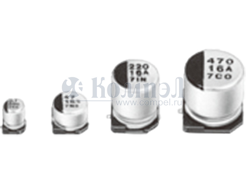
    В начале этого года линейка электролитических конденсаторов Panasonic пополнилась компактными алюминиевыми конденсаторами серии FN. В рамках новой серии анонсировано более 150 различных изделий. Серия конденсаторов FN является продолжением серий... ...читать

    21 июня 2019
    статья

    Конденсаторы Panasonic. Часть 1. Алюминий

    Виктор Чистяков (г. Малоярославец) Известная уже 100 лет своими инновациями компания Panasonic даже в столь традиционные изделия как алюминиевые электролитические конденсаторы ухитряется вносить оригинальные и полезные конструктивные дополнения.... ...читать