EEEFK0J271SL

Конденсатор алюминиевый 6.3 В x 270 мкФ ±20%, SMD, -55...105 °C
развернуть ▼ свернуть ▲

Технические характеристики

показать свернуть
Ёмкость номинальная
Допуск по ёмкости
Напряжение номинальное
Температура рабочая
Диаметр корпуса
Высота корпуса
Способ монтажа
Эквивалентное последовательное сопротивление
Ток пульсаций низких частот
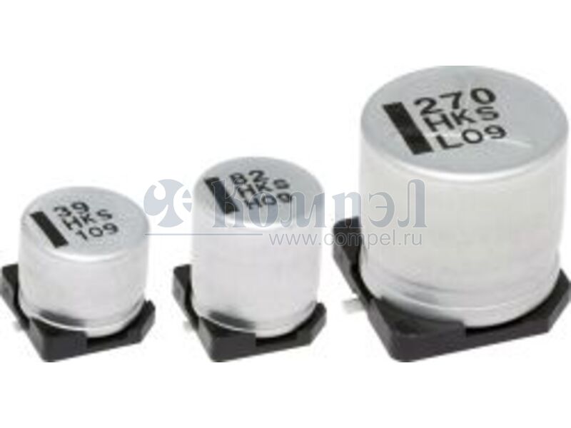
Диаметр x Высота 6.3×6.3×6.6 мм
  Примечание: Aluminum Electrolytic Capacitor, Polarized, Aluminum (wet), 6.3V, 20% +Tol, 20% -Tol, 270uF, Surface Mount, 2626
Нашли ошибку? Выделите её курсором и нажмите CTRL + ENTER

Аналоги 7

показать свернуть
Тип Наименование Корпус Упаковка i Ёмкость Допуск Напряжение Температура рабочая Срок службы Диаметр Высота Способ монтажа Шаг ESR Импеданс Ток пульсаций НЧ Ток пульсаций ВЧ Применение Примечание Карточка
товара
P= EEEFN0J271UL (PAN)
 
Aluminum Electrolytic Capacitor, Polarized, Aluminum (wet), 6.3V, 20% +Tol, 20% -Tol, 270uF, Surface Mount, 2626
P- EEEFN0J271UP (PAN)
 
в ленте 1000 шт V-FN, 6.3V, 270uF, 105°C, 2000h, 6.3x5.8mm, ripple 240mArms, 0.36Ohm
P- EEEFK0J271SP (PAN)
 
1000 шт Aluminum Electrolytic Capacitor, Polarized, Aluminum (wet), 6.3V, 20% +Tol, 20% -Tol, 270uF, Surface Mount, 2626
A+ EEEFN0J271UV (PAN)
 
1000 шт V-FN, Vibration proof, 6.3V, 270uF, 105°C, 2000h, 6.3x5.8mm, ripple 240mArms, 0.36Ohm
A+ EEEFK0J271SV (PAN)
 
1000 шт
 
Aluminum Electrolytic Capacitor, Polarized, Aluminum (wet), 6.3V, 20% +Tol, 20% -Tol, 270uF, Surface Mount, 2626
A+ 10SVP270M (PAN)
 
500 шт
A+ 10SVPC270M (PAN)
 
1000 шт

Файлы 2

показать свернуть
Aluminum Electrolytic Capacitors Surface Mount Type Halogen-free FKS series 6.3 V to 50 V 63 V to 100 V : High temperature Lead-Free reflow : Standard Lead-Free reflow Features ● ● ● ● Country of origin Endurance:105 ℃ 2000 h 1 size smaller than series FK AEC-Q200 compliant RoHS compliant ● Malaysia Specifications Category temp. range Rated voltage range Capacitance range Capacitance tolerance Leakage current Dissipation factor (tan δ) Characteristics at low temperature Endurance Shelf life Resistance to soldering heat –55 ℃ to +105 ℃ 6.3 V to 100 V 27 μF to 1800 μF ±20 % (120 Hz / +20 ℃) I ≦ 0.01 CV or 3 (μA) After 2 minutes (Whichever is greater) Please see the attached characteristics list Rated voltage (V) 6.3 10 16 25 35 50 63 80 100 Z (–25 ℃) / Z (+20 ℃) 2 2 2 2 2 2 2 2 2 (Impedance ratio at 120 Hz) Z (–40 ℃) / Z (+20 ℃) 3 3 3 3 3 3 3 3 3 Z (–55 ℃) / Z (+20 ℃) 4 4 4 3 3 3 3 3 3 After applying rated working voltage for 2000 hours at +105 ℃ ± 2 ℃ and then being stabilized at +20 ℃, capacitors shall meet the following limits. Capacitance change Within ±30 % of the initial value Dissipation factor(tan δ) ≦ 200 % of the initial limit Leakage current Within the initial limit After storage for 1000 hours at +105 ℃ ± 2 ℃ with no voltage applied and then being stabilized at +20 ℃, capacitors shall meet the limits specified in endurance. (With voltage treatment) After reflow soldering and then being stabilized at +20 ℃, capacitors shall meet the following limits. Capacitance change Within ±10 % of the initial value Dissipation factor(tan δ) Within the initial limit Leakage current Within the initial limit Frequency correction factor for ripple current Frequency (Hz) Correction factor 120 0.65 10 k 0.95 100 k to 1.00 Dimensions Example : 6.3 V 270 μF Marking color : BLACK A±0.2 K 0.3 max. Rated voltage code Pressure Relief (ø10 and larger) (P) W (I) B±0.2 L H Series identification H 270 j KS Capacitance (μF) øD±0.5 Negative polarity marking (–) (I) Marking 1k 0.85 ()Reference size Lot number R.voltage code j A C E V 6.3 10 16 25 35 Unit:V H J K 2A 50 63 80 100 Unit:mm Size code D D8 F G øD L A, B 6.3 5.8±0.3 6.6 6.3 7.7±0.3 6.6 8.0 10.2±0.3 8.3 10.0 10.2±0.3 10.3 H 7.8 max. 7.8 max. 10.0 max. 12.0 max. I 2.6 2.6 3.4 3.5 W 0.65±0.1 0.65±0.1 0.90±0.2 0.90±0.2 Design and specifications are each subject to change without notice. Ask factory for the current technical specifications before purchase and/or use. Should a safety concern arise regarding this product, please be sure to contact us immediately. P K +0.15 1.8 0.35 ー0.20 +0.15 1.8 0.35 ー0.20 3.1 0.70±0.2 4.6 0.70±0.2 13-Mar-20 PDF
Документация на EEEFKJ471XSL 

Series catalog

Дата модификации: 24.09.2021

Размер: 508.8 Кб

9 стр.

Aluminum Electrolytic Capacitors Surface Mount Type Halogen-free FKS series 6.3 V to 50 V 63 V to 100 V : High temperature Lead-Free reflow : Standard Lead-Free reflow Features ● ● ● ● Country of origin Endurance:105 ℃ 2000 h 1 size smaller than series FK AEC-Q200 compliant RoHS compliant ● Malaysia Specifications Category temp. range Rated voltage range Capacitance range Capacitance tolerance Leakage current Dissipation factor (tan δ) Characteristics at low temperature Endurance Shelf life Resistance to soldering heat –55 ℃ to +105 ℃ 6.3 V to 100 V 27 μF to 1800 μF ±20 % (120 Hz / +20 ℃) I ≦ 0.01 CV or 3 (μA) After 2 minutes (Whichever is greater) Please see the attached characteristics list Rated voltage (V) 6.3 10 16 25 35 50 63 80 100 Z (–25 ℃) / Z (+20 ℃) 2 2 2 2 2 2 2 2 2 (Impedance ratio at 120 Hz) Z (–40 ℃) / Z (+20 ℃) 3 3 3 3 3 3 3 3 3 Z (–55 ℃) / Z (+20 ℃) 4 4 4 3 3 3 3 3 3 After applying rated working voltage for 2000 hours at +105 ℃ ± 2 ℃ and then being stabilized at +20 ℃, capacitors shall meet the following limits. Capacitance change Within ±30 % of the initial value Dissipation factor(tan δ) ≦ 200 % of the initial limit Leakage current Within the initial limit After storage for 1000 hours at +105 ℃ ± 2 ℃ with no voltage applied and then being stabilized at +20 ℃, capacitors shall meet the limits specified in endurance. (With voltage treatment) After reflow soldering and then being stabilized at +20 ℃, capacitors shall meet the following limits. Capacitance change Within ±10 % of the initial value Dissipation factor(tan δ) Within the initial limit Leakage current Within the initial limit Frequency correction factor for ripple current Frequency (Hz) Correction factor 120 0.65 10 k 0.95 100 k to 1.00 Dimensions Example : 6.3 V 270 μF Marking color : BLACK A±0.2 K 0.3 max. Rated voltage code Pressure Relief (ø10 and larger) (P) W (I) B±0.2 L H Series identification H 270 j KS Capacitance (μF) øD±0.5 Negative polarity marking (–) (I) Marking 1k 0.85 ()Reference size Lot number R.voltage code j A C E V 6.3 10 16 25 35 Unit:V H J K 2A 50 63 80 100 Unit:mm Size code D D8 F G øD L A, B 6.3 5.8±0.3 6.6 6.3 7.7±0.3 6.6 8.0 10.2±0.3 8.3 10.0 10.2±0.3 10.3 H 7.8 max. 7.8 max. 10.0 max. 12.0 max. I 2.6 2.6 3.4 3.5 W 0.65±0.1 0.65±0.1 0.90±0.2 0.90±0.2 Design and specifications are each subject to change without notice. Ask factory for the current technical specifications before purchase and/or use. Should a safety concern arise regarding this product, please be sure to contact us immediately. P K +0.15 1.8 0.35 ー0.20 +0.15 1.8 0.35 ー0.20 3.1 0.70±0.2 4.6 0.70±0.2 13-Mar-20 PDF
Документация на серию FKS 

Series catalog

Дата модификации: 18.08.2021

Размер: 511.8 Кб

9 стр.

    Внимание! Точность указанного на сайте описания товара не может быть гарантирована. Для получения более полной и точной информации о товаре смотрите техническое описание (Datasheet) на сайте производителя.